
Digital Rebar Provision (DRP) is an automation platform that is unique for its ability to interweave and combine different types of automation. The technology is capable of "automating your automation" by robustly integrating industry standard tools like Ansible, Terraform and Kubernetes. Perhaps even more cool is its ability to manage the lifecycle of bare-metal. Taken together, DRP can manage your physical and digital infrastructure and its lifecycle, or be your "The Continously Integrated Data Center". Catalogs of content provided by RackN and the community make available things like cloud API-specific and hardware-specific tooling. If you're a DevOps practitioner on the lookout for the "new shiny" to up your skillset with, I wholeheartedly endorse the product. My professional experience with DRP left me longing to continue using it, and that's the point of this blog post.
The Goal
The goal is to create a highly available DRP deployment on a collection of Raspberry Pis to serve as the cornerstone for further automation projects. Thus, the project's anatomy is similar to RackN's EdgeLab, but the purpose is inverted: the hardware's purpose to run DRP itself, as opposed to serving as a target to run automation against. Rest assured, I've had my eyes on another project to serve as my automation target, but Mr. Geerling barely got his hands on one, so that's a little ways down the road still. All the more reason to have DRP ready to go when the Turing Pi 2 launches!
The Plan
The plan is to assemble a collection of Raspberry Pis and install DRP in High Availability (HA) mode on them. The software portion will be in a follow-on blog post, but this one will focus on the hardware wrangling and document the details so you can build your own!
The Hardware
The increased demand for Raspberry Pis over the last few years combined with the chip shortage has resulted in severe scarcity and corresponding price increases. Getting your hands on them now is expensive, so it might make sense to wait a while. However, if you're like me (lack patience) and want to go ahead and bite the bullet, read on for the hardware list that came together for the end product.
- 4x Raspberry Pi Model 4Bs
- 4x 64GB MicroSD cards
- 4x Waveshare PoE Hat (B)s
- 1x Netgear GS308EPP PoE+ Switch
- 1x C4LabsCloudlet Cluster Case
- 1x pack of M2.5 4mm+6mm brass standoffs
Why These Components, Specifically?
I went for the 8GB RAM model Pis. DRP requires at least 4GB RAM, but the last thing I want is hardware limitations to become my undoing. And why 4? DRP HA requires at least 3 nodes in a cluster, and the 4th is to serve as the load balancer.
As you saw in DRP's hardware requirements, 60GB of storage is recommended. Depending on how much content your DRP install holds, you may need even more; it's common to upload operating system ISOs to be stored on the DRP nodes' filesystems, so those eat up space in a hurry. And that's on top of the Catalog Content you install and logs generated over the course of operations, so 64GB is a reasonable starting point. Why these particular SD cards? Because Tom recommended them. These were assessed as the most performant (not to mention cheapest), so that was enough for me. I am weary of the longevity of the cards, however; after prolonged write operations, it's conceivable that the cards might start to die. That's part of the drive for deploying DRP in HA mode, and why Samsung's Endurance card would be my runner-up pick.
I wanted to use a PoE Hat to reduce cable clutter, and the official PoE Hat is about as scarce as the Pis themselves. I didn't initially want to take a chance on 3rd party hats for risk of them somehow frying the Pis, but after reading Jeff's blog post reviewing the official PoE+ hat, I decided in the name of smaller power bills to take a chance on a 3rd party PoE hat in lieu of a PoE+ hat. The Waveshare hat had what I was looking for and more: it extends the GPIO pins to make them available for the Cloudlet case fans, it leaves enough room for small heatsinks on the Pis, and it comes with an OLED display to boot!
Given all the above for power draw considerations, I didn't much like the idea of having to buy another switch because a regular PoE switch couldn't provide enough juice. There was no guarantee that the hats would function well anyway, so I hedged my bet on getting a PoE+ switch; if the hats didn't work out, I could always get PoE+ hats and not have to worry about buying another switch. I also wanted a switch that allowed me to remotely toggle the power supply to individual ports in order to fully shut down the Pis and power them up without having to manually unplug and replug the ethernet cables.
The Cloudlet case was recommended in RackN's EdgeLab, and I liked an option that encompassed the switch. I opted for the clear version that way I could read the OLED display on the PoE hat.
Finally, I painfully learned the proper size standoffs to combine that will both allow the individual Pis to be mounted onto the Cloudlet's plastic mounts and allow all of the mounted Pis to fit within the case. I say painful because Home Depot, Lowes, and Walmart didn't carry anything in stock to physically assess before purchase and popular online retailers for hardware like Grainger just didn't carry standoffs that matched the specifications I thought I needed. In the end, it was Amazon that carried what I thought was going to have to be a specialty order, who would have thought?
The Journey
Pis and Hats
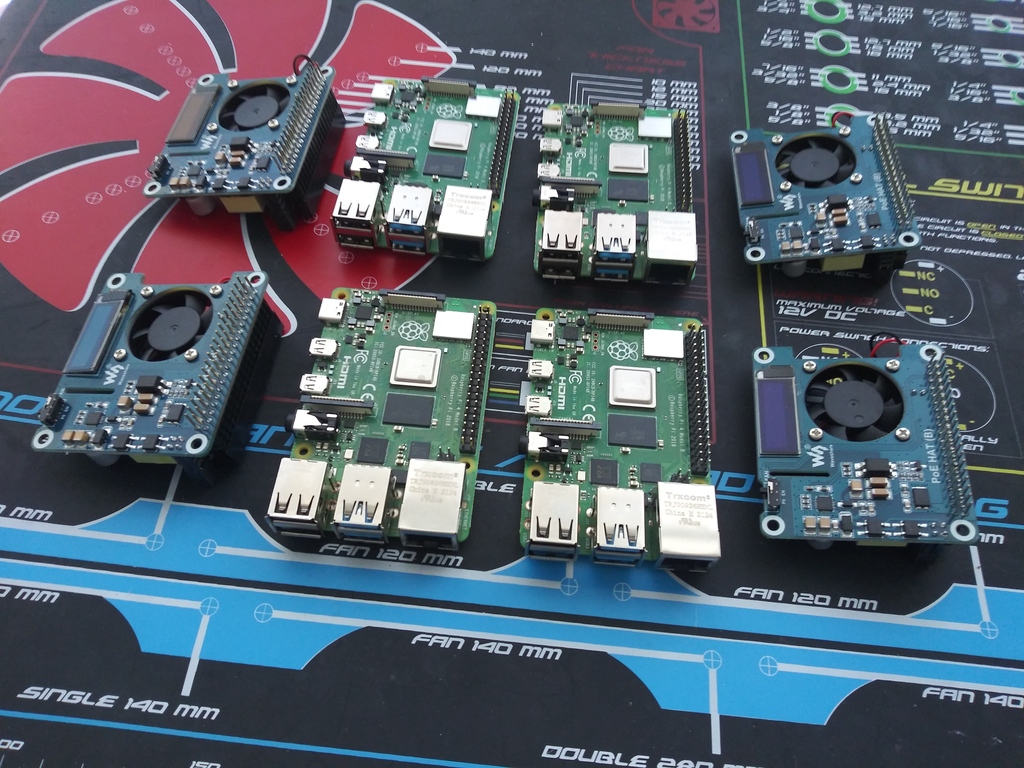
The first step was to layout the work area with the various parts on an anti-static mat.
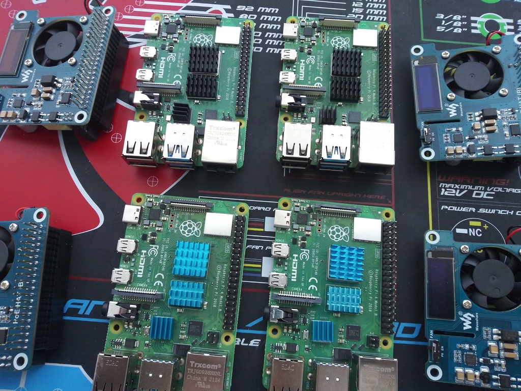
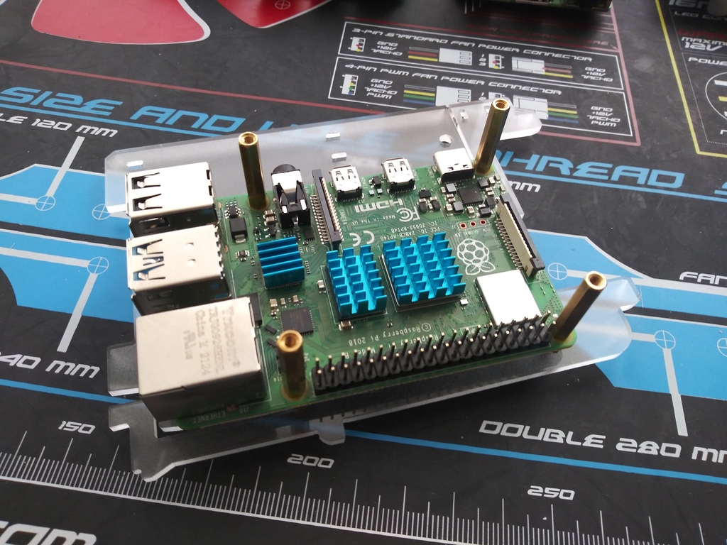
Next, I applied the heatsinks.
Pis with Heatsinks Applied
Before installing the PoE hats, I made sure to slightly tuck their fan cables under the corner of the fans to prevent them from dangling onto the CPU's heatsink and risk getting melted.
Slightly Tucking-in the Fan Cable
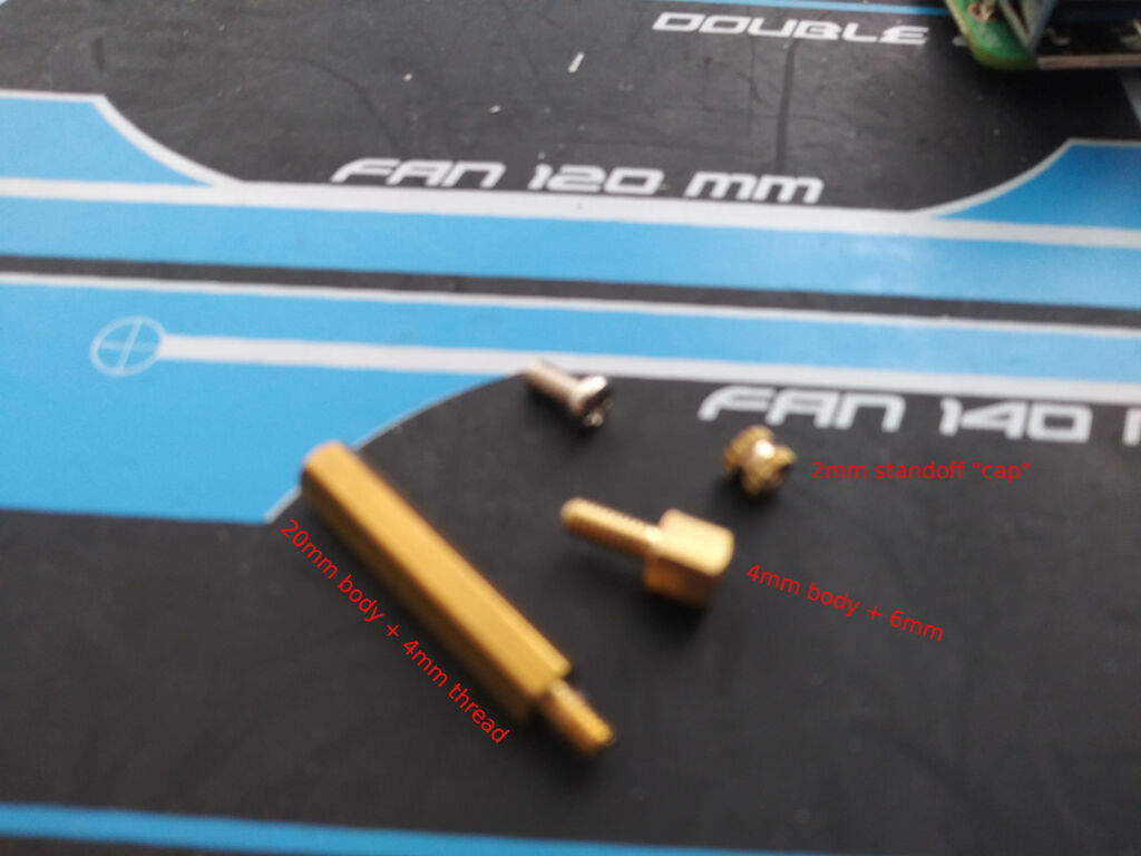
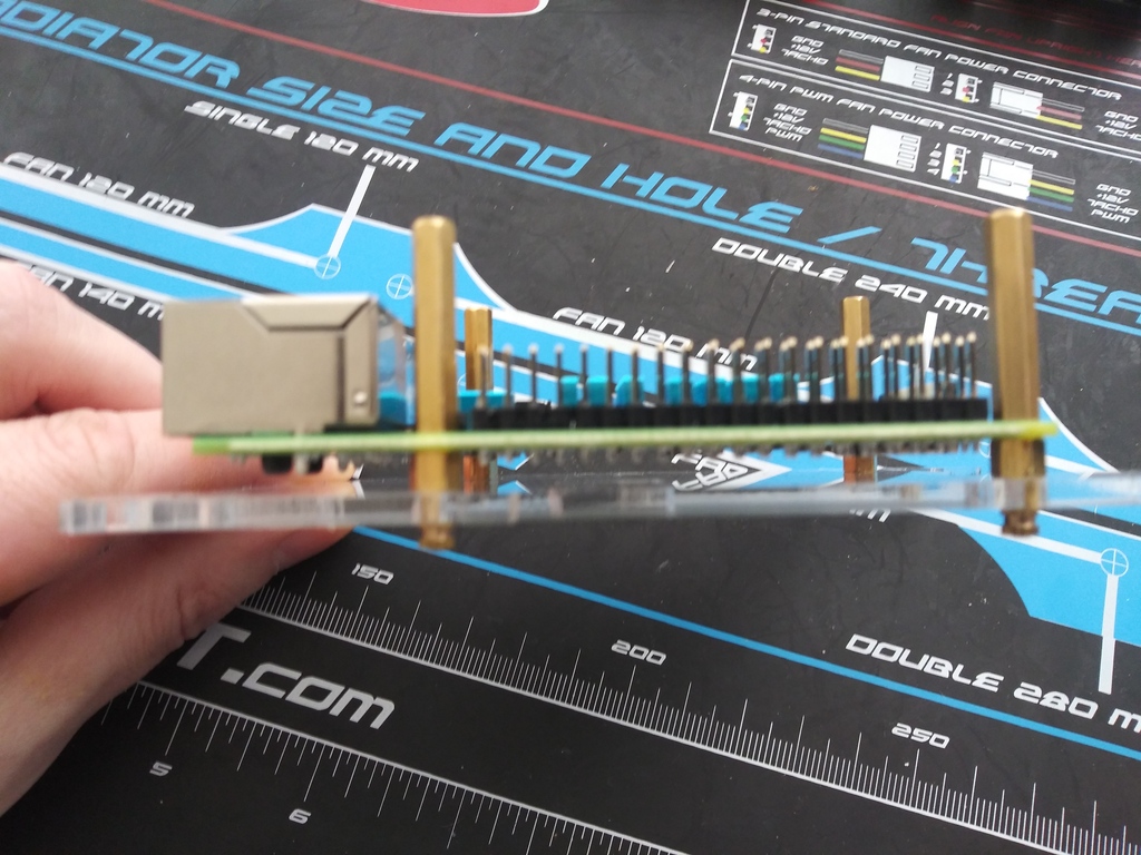
The primary roadblock in the assembly was the standoff spacers that allowed the Pis with the PoE hats to be mounted on the case's plastic mounts. The Waveshare PoE hats came with 20mm + 4mm brass, hex standoffs. That's a 20mm body with a 4mm thread. Of course that was sufficient for attaching the hat to the Pi, but after the 4mm thread went through the Pi's board, there wasn't enough thread to route through a spacer, one of the case's plastic mounts, and be capped off with another spacer underneath the plastic mount. I figured I'd need 7-8mm of thread to go through all of those pieces, but after exhaustive searching, I could only conclude that threads for spacers most commonly come in 4mm, and a few with 6mm, and that's it. So there was no one piece in existence that I could use to bring everything together.
Which means multiple pieces were needed. The first spacer was perfect for attaching the hat to the Pi, but I needed another spacer to standoff the Pi from the plastic mount and have sufficient thread leftover to fit through the plastic mount (about 3mm thick) and attach a final spacer cap. I needed this extra piece to minimize space between the Pi and plastic mount and not leave extra thread hanging out unused, otherwise all 4 Pis would not be able to fit within the case because the assembly of each would be too tall! The M2.5 standoff with a 4mm body and 6mm thread ended up being perfect.
Standoffs and Spacers Used
I first mounted the Pis on the plastic mounts using both the 20mm and 4mm spacers, with the 4mm spacers between the Pi board and the plastic mount. A 2mm spacer/cap that came with the Cloudlet case was used on the thread underneath the plastic mount.
Pi on Plastic Mount
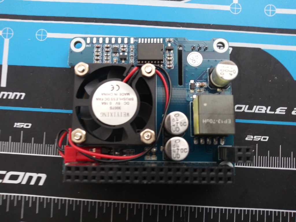
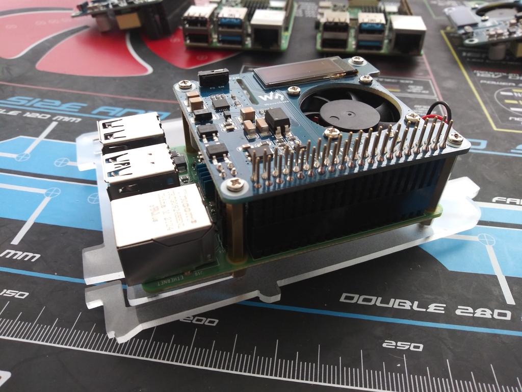
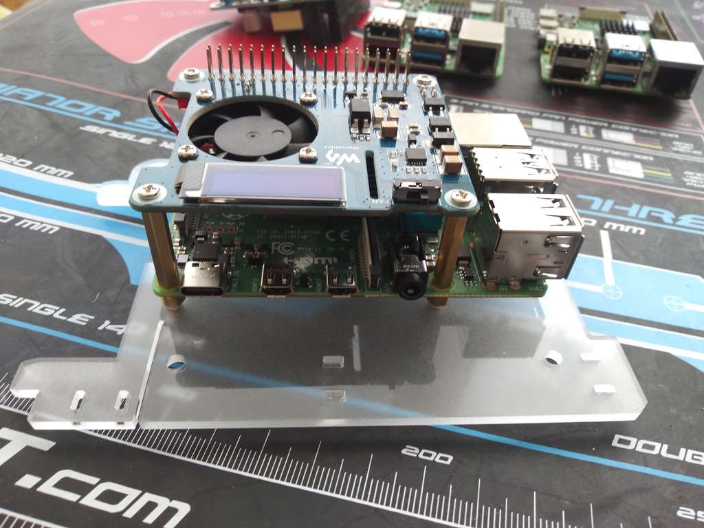
Next I installed the PoE hat onto each Pi.
Pi with PoE Hat
It was at this point I detoured to format the SD cards with an operating system before proceeding with mounting the Pis into the case, because the card slots would be inaccessible after mounting. I'll cover the OS install in the next blog post.
With the SD card flashing and physical mounting done, all that was left to do was see if all 4 could fit in the case and still have the cases' fans plugged in. I routed the fan cables through the extra slots in the case intended to serve as mount points; with the PoE Hats installed, there was no way 8 Pis would be able to fit in the case anyway, so maybe each Pi could get away with 2x the space used.
Installing the Case Fans
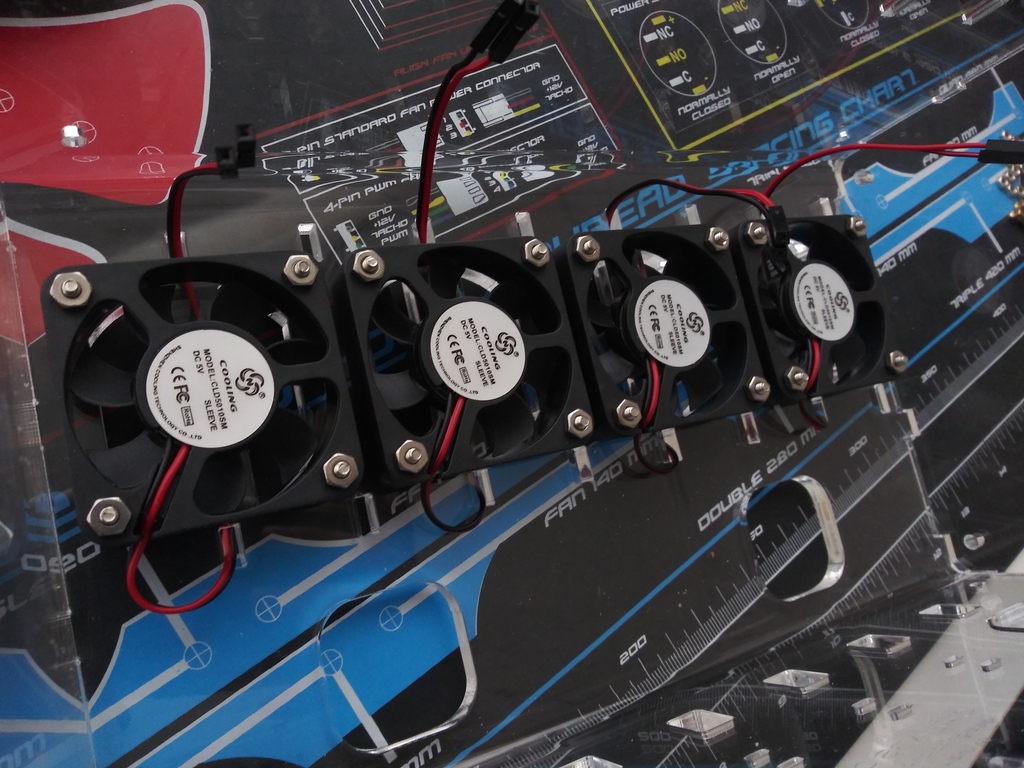
Thank goodness that turned out to be the case! There was just enough space to attach the case fans to the raised GPIO pins.
4 Pis, Each Using 2x the Space in an 8 Pi Case
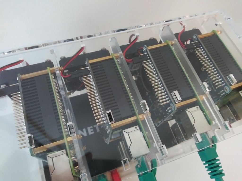
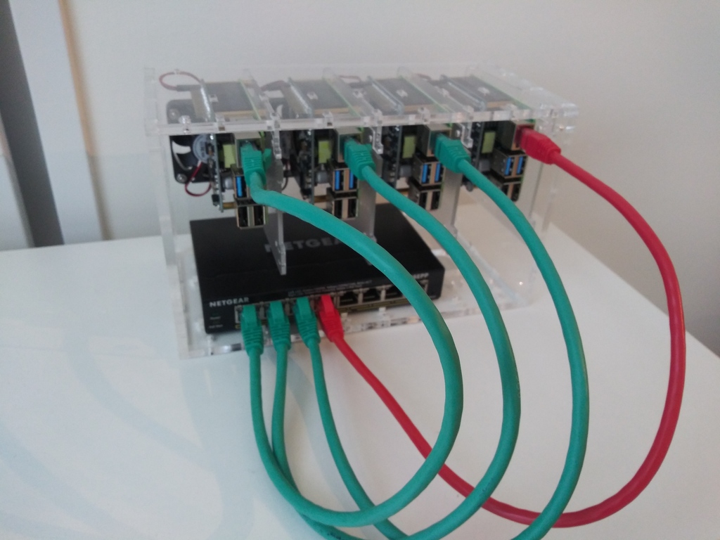
The final assembly came together and the ethernet cables politely obliged the drastic bending asked of them.
Final Assembly
Thermals and Power Management
Was the cooling overkill? Did I really need the PoE hat's fan, the case fans, and heatsinks? A quick Google search suggests a vanilla PI setup without thermal controls leaves the Pis running 20-30 degrees Celsius higher than room ambient temperature; if the room temperature is 68 degrees Fahrenheit, that's 20 degrees Celsius, meaning the standard temperature range is 40-50 degrees Celsius at idle. With the heatsink and both fans running, the internal temperature hovers at 26-27 degrees Celsius. If I disable the PoE hat's fans, the temperature increases to 28-29 degrees Celsius. So I'd say it's nice to have control over the magnitude of active cooling applied, and the passive cooling doesn't hurt.
And how did the PoE switch work out? In an ideal world, a small switch would have an API to automate such actions, but that's unfortunately a feature outside the budget of the switch I chose. I was also quite disappointed that the switch's web interface does not support HTTPS, full stop. Not even an embedded self-signed certificate. And it's not that it's simply disabled by default; it straight-up is not even possible to use HTTPS on this thing. So there is no way to prevent your login creds from being passed across the network in the clear, which, suffice it to say, I'm not really thrilled about. And yes, I did download and apply the latest firmware right away. Despite this shortcoming, the switch is able to accomplish what I wanted via its web interface.
PoE Port Force Cycle
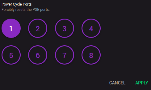
If you have ran the poweroff command on your Pi to shutdown the OS, the PoE is still going full force and the fans and OLED display remain powered up. By using the appropriately named "Power Cycle Ports" section of the web interface, you can cycle power to the port resulting in the Pi booting back up into its OS.
PoE Port Disable/Enable
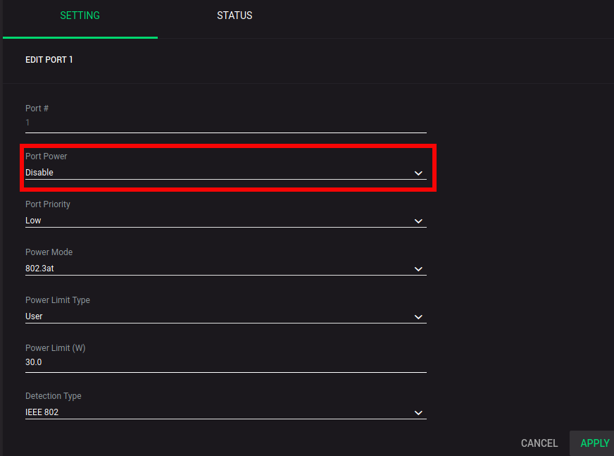
To cut the power entirely after use, you must use the section below the first to disable power to the port. Make sure you shut down the OS first so you don't risk the power-cut messing up an in-progress write to the SD card, then simply disable the power to the port. The fans and OLED display will power off. When you come back and enable the port, the Pi will boot back up.
Conclusion
It took a while to get all of the parts delivered and troubleshoot the proper standoff measurements, but I'm pretty pleased with the result. It's great to finally have the Pis assembled and ready for the real work: software. In the next blog post, I'll catalog the OS install, PoE hat configuration, and DRP install and setup.